
In this blog I’d like to share some of the things that were, at first, confusing to me about Q-SYS. It is specifically for those who are just starting their journey with this incredible, yet intricate and ever-expanding program.
Disclaimer: If you are a Q-SYS Super User you might want to skip this blog. It really is intended for beginners.
I do work for QSC, but since I wasn’t involved with the creation or design of Q-SYS Designer Software, this isn’t bragging when I say what an incredible job the developers did.
The program is amazingly well thought-out. The UI is intuitive; access to what you need most often is within easy reach, and the drag and drop functionality and virtual wiring makes using the program straightforward and even fun.
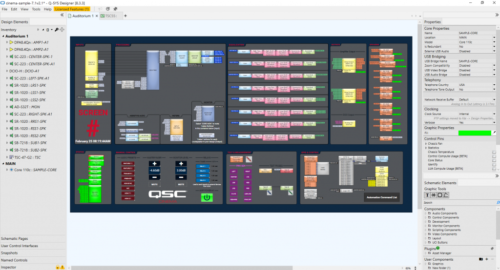
As Training Manager, I have graded hundreds of Q-SYS Level One for Cinema exams, yet, the program is so deep, I still consider myself a Q-SYS beginner. I remember the very first thing that confused me about the program. Q-SYS is comprised of “components” that you wire together to route audio through various phases of processing based on your needs. Most represent virtual connections, but a few of these components actually represent physical connectors on physical hardware devices (peripherals).
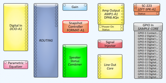
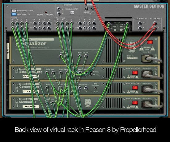
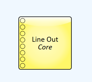
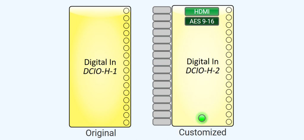
These components are all explained very well in our Q-SYS Level 1 for Cinema course found here. But notice that the “Digital In DCIO” component (top left,) for example, says it’s an input but only has output pins. Likewise, the “Line Out-Core” only has input pins. This left a newbie like me wondering; “Is there anything that represents the audio signal that is going IN to the “IN” components and OUT of the “OUT” components? See, I’m a Pro Tools guy; totally different concept. And I use Propellerhead’s Reason program frequently too. Both are for audio recording. So here’s what I was used to:
Turns out, with Q-SYS you must assume physical wires are connected to these devices and understand that you won’t see them represented inside the software design. But what if there is no wire plugged into that physical connector? How will you know?

All this to say, I was confused when Fig. A didn’t look like Fig. B when an actual physical connection was made on a device.
The revised graphic above (Fig. B) would represent two RJ45 connectors that enter into the DCIO rear panel, each delivering 8 channels of audio via AES3.

I also wondered why Fig. C wasn’t designed with indicators like I mocked up in Fig.D when physical wires are connected (or are not connected.)
So I asked, and after a few great conversations with our Q-SYS development team I learned that exposing the status to the outside of the component block would be possible in some cases, if our customers asked for it; but they haven’t. (Yes, I’m feeling a little bit lonely on this one.) Just know this: In places where status can be determined it is displayed inside the component’s control panel. In Q-SYS it is very simple to add these indicators to the graphic of a component with an easy copy, paste, and customize process. This is even better, because you are not limited to our design, and you can modify it in a way that works best for you.
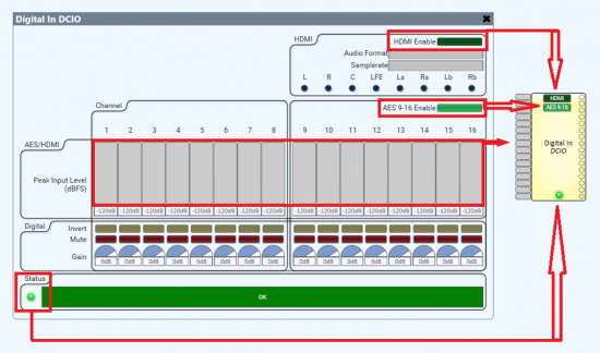
However, in other areas it’s just not technically feasible to get the status at all. With signals like AES inputs we do get status that audio is streaming but that’s not the same as detecting when a wire is plugged into the back of a peripheral. Some specific types of microphones allow us to tell if one is connected by sending a pilot tone and reading the signal back using our Flex I/O, but with most signals like analog inputs or outputs, there’s really no way to determine if something is plugged in.
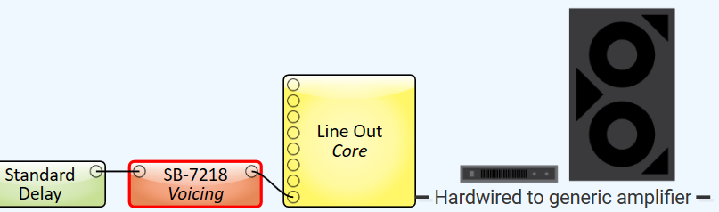
One component I knew for sure implied a physical connection to a physical device; the loudspeaker voicing component. It looks (basically) like this when connected in a typical design:
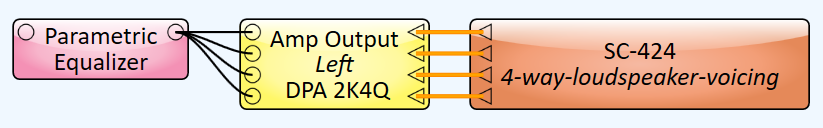
Makes sense, right? A processed signal goes into the amplifier, out of the amplifier, to a loudspeaker. Not quite.
This “voicing” component is actually sending settings (DSP, EQ, Crossover, Voltage limiter, etc.) to the DPA-Q amplifier rather than to the Core where most signal processing is performed. So, if displayed in a correct linear fashion, shouldn’t this “voicing” component be placed BEFORE the amplifier? One reason it comes after, even though it is sending data TO the amplifier, is because this better represents the physical wiring of the system. Great for people just like me who want to imagine that the loudspeaker (voicing) block represents the end of the line.
What’s is actually happening though is a bit closer to the graphic below.
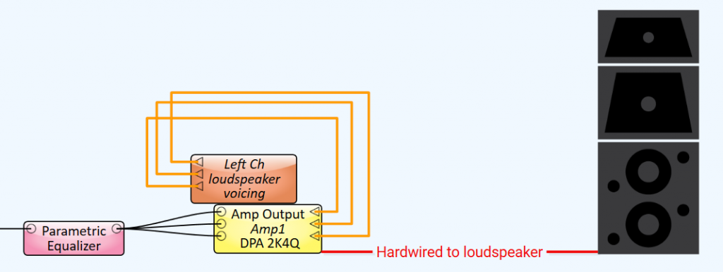
Important to note, it’s also possible to the move the DSP workload out of the DPA-Q amplifier or the Dataport card by using “inline processing”. This configuration shifts DSP for the speaker voicing and crossovers away from the amp to the Core and can be useful when outputting signal to generic amplifiers. However, you do lose the limiter functionality. In this case, it would look similar to this:
Maybe it’s just me, but I’m being honest; these things threw me off at first.
Like any other new program, this, and other misconceptions are usually resolved with time spent working in the program. There is an operating mode called Emulation Mode which utilizes your own CPU to simulate your design so you don’t have to have a Q-SYS Core processor on hand to create designs and practice. This mode allows you to test not all, but many operations and adjust settings as if you were operating in “Live” mode. I suggest you use it, a lot. Because there is no substitute for practice. Another thing I did early on, before I had access to real devices, was create images of the most commonly used Q-SYS devices in cinema, a Core 110c and a DCIO-H, with graphics of the Q-SYS component next to each input or output connector that it represents.
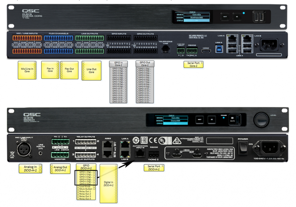
It was posted on my wall for reference while I went through the online course and helped me visualize how these components related to what was happening inside my designs.
The video course for Level One for Cinema is top-notch. It is engaging, often hilarious, and delivers all the information you’ll need to gain a basic understanding of the software. If you haven’t taken the course, do. It is delivered in bite-sized chunks you can ingest at your own pace, and makes learning a new program a lot easier.
In a future post I’ll discuss some of the most common issues I see from new users and try to help clarify some concepts and misunderstandings. Was this blog helpful to you as a beginner in Q-SYS? Let us know.