In the history of professional audio, the introduction of QSC Directivity Matched Transition® (DMT™) technology has been one of those ‘lightbulb moment’ innovations that forever changed how audiences experience sound. In order to fully grasp its benefits, and why DMT is foundational to QSC loudspeaker design, let’s start with some fundamentals of the physics of sound.
Radiation Space
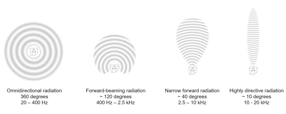
Sound propagates through air in different ways depending on frequencies, and as shown below it spans from omnidirectional radiation at low frequencies to highly directive propagation at high frequencies. Between these two extremes, the behavior is a slowly changing pattern with varying frequencies. As we are going to discuss loudspeaker design, we need to keep this in mind.
Loudspeaker Woofer Coverage
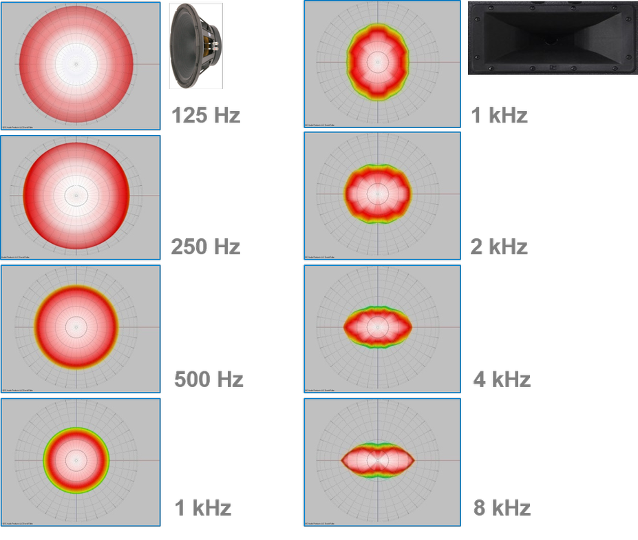
In a typical 2-way loudspeaker design, the woofer and the HF driver will share the task of reproducing the full audio spectrum. Any woofer will display a fully omnidirectional radiation behavior from the lowest frequency it can reproduce to approximately 400 Hz. From this point upwards, the sound radiation will gradually become directional (in a conical-type shape). Now, at the crossover frequency where the HF driver – and its associated horn – is taking over (typically between 1 and 2.5 kHz), the woofer’s conical-shaped coverage has become more narrow. Here the size of the woofer’s cone dictates the actual radiation behavior. For a given crossover frequency (say 1 kHz with a wavelength of 34 cm / 13.4 in), as soon as the radiated wavelength is smaller than the woofer’s cone size, the sound becomes strongly directional. Therefore, at 1 kHz, a small diameter woofer’s cone (smaller than 34 cm / 13.4 in) will be less directional than a larger one (equal or larger than 34 cm / 13.4 in).
Now, many loudspeaker designs ignore this acoustic phenomenon and publish only the high frequency horn coverage in their specifications. However, this is misleading, as the stated coverage is not attained over the critical, ear-sensitive, midrange bandwidth, which extends below the crossover frequency. In reality, a smooth, directional transition from woofer to horn makes a world of difference. Having a well-behaved coverage will enable proper loudspeaker equalization and balanced reproduction once loudspeakers are placed in real rooms.
When designing a 2-way loudspeaker, the first step is to understand how the selected woofer coverage is behaving, documenting the natural coverage pattern of each specific woofer size and model (examples in Figure 3, 5 and 6 below).
Conventional Horn Design and Coverage
Loudspeaker designers have long used rectangular-shaped horns to efficiently direct high frequencies to cover the audience area. While it is true that such horns can deliver some control coverage at higher frequencies (typically above 4 – 8 kHz) where the horn width and height are larger than the wavelengths radiated by the HF driver, issues arise at midrange frequencies where the horn dimensions, especially the height, are now smaller than the wavelengths they are attempting to guide (around 1 – 3 kHz).
When the horn height is very short, the vertical coverage pattern control of lower frequencies collapses earlier than the horizontal coverage pattern, creating inconsistent off-axis sound reproduction versus frequency, commonly called off-axis sound coloration.
Therefore, trying to combine a typical horn (90° x 50°) with an 8- or a 12-inch woofer using the same crossover frequency will yield very different results. Beaming less at the crossover frequency, small woofers exhibit wide coverage (90°- 105°), while larger woofers display a narrower pattern (60°- 75°). These woofer-horn coverage specifications do not match in either the vertical or the horizontal planes.
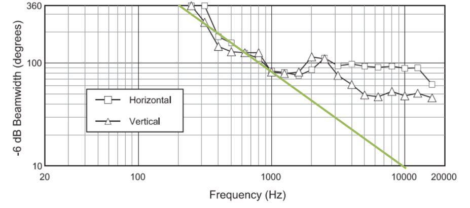
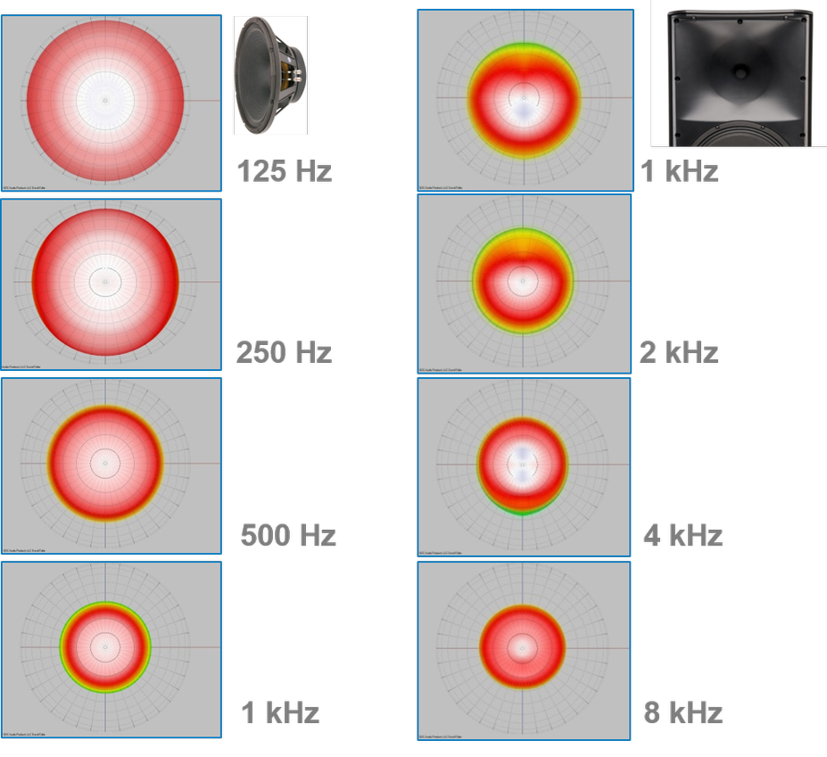
Additionally, if only the horn width and its associated horizontal directivity matches the inherent woofer coverage, but not the height, the resulting vertical off-axis response will be gnarly, and the loudspeaker power response(1) will be degraded. Figure 3 below shows a conventional loudspeaker featuring a 12-inch woofer with a 90° x 50° HF horn, where the woofer coverage approximates pistonic radiation up to 1 kHz. If the horizontal directivity is fairly well controlled (with remaining problems between 1 and 3 kHz), the vertical directivity control is lost above 4 kHz.
With a better understanding of the above principles of transducers’ physics, QSC developed proprietary designs, which select the optimal crossover frequency for a desired HF driver, mounting it into a horn with a geometry and coverage pattern that perfectly matches the woofer’s coverage at the selected crossover point.
How does DMT work?
Allowing the horn shape to match the high-frequency driver coverage angle to the coverage angle of the woofer at the crossover frequency is what QSC DMT does, bringing considerable sonic benefits.
In fact, DMT horns match boththe width and height of the waveguide to the woofer’s coverage at crossover frequency yielding very smooth off-axis response and an optimized power response, which removes, in most cases, the need to equalize the loudspeakers once placed in a room.
Another interesting aspect is that smaller woofers typically have lower sensitivity(2), but at the same time, their adequately matched DMT horns radiate sound energy over a wider area, and therefore their horns on-axis sensitivity is lower by the same order of magnitude. Larger woofers have higher sensitivity, but their matching narrower DMT horns also have higher on-axis sensitivity, by the same order of magnitude. In that way, the DMT technology greatly improves the sound reproduction quality, on- and off-axis, without creating compromise on the overall loudspeaker sensitivity and efficiency.
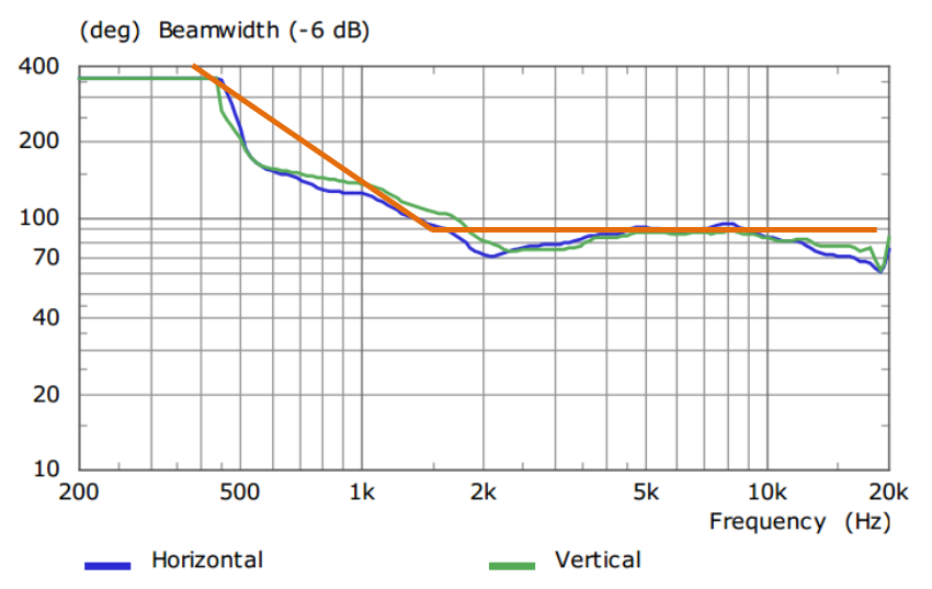
Figure 5 below illustrates a QSC loudspeaker featuring a 10-inch woofer combined with a 90° x 90° DMT HF horn. The beamwidth design target is indicated in orange, where the 10-inch woofer natural coverage pattern is used up to 1.5 kHz. At that frequency, it is necessary to transition to the HF driver, as the woofer itself cannot reproduce the needed wavelengths. As shown in the graph, the corresponding beamwidth at 1.5 kHz is 90 degrees, which defines the coverage target for the horn design.
The measured horizontal and vertical coverage pattern are also provided to illustrate how close they match the target design criteria.
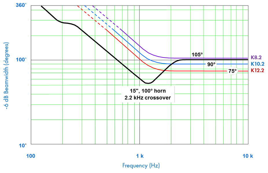
In the next figure 6, the black line shows the coverage pattern of a conventional 15-inch, 2-way loudspeaker with a rectangular 100° x 60° horn. Below the 2.2 kHz crossover point, the coverage narrows to 50 degrees (meaning 25 degrees on either side of the on-axis response), while the coverage above 2 kHz widens to 100 degrees.
Let’s consider a conventional loudspeaker design and see what are the implications for the audience, particularly the listeners who are off-axis from the loudspeaker. Listeners who are as little as 30 degrees off-axis will be hearing far less midrange than the on-axis listeners. One obvious and common result of this loss of midrange is lack of intelligibility. If you have ever heard an announcement or speech that had plenty of volume, but still had difficulties understanding what was being said, off-axis loss of midrange was likely the culprit. Of course, the sound engineer could equalize the system so that the loudspeaker reproduces more midrange to compensate for this off-axis loss. However, doing so, the on-axis listeners will be hearing significant excess of midrange at the same time – a very unpleasant experience. The unbalanced on- and off-axis sound reproduction cannot be compensated without creating more compromises. The solution has to lie in the loudspeaker design itself.
QSC K.2 Series loudspeakers – like many other QSC models – feature perfectly-matched low- and high-frequency woofers and horns. The 8-inch woofer in the K8.2 will cover 105 degrees at the crossover frequency and therefore the horn design will be based on those criteria. The K10.2 and K12.2 respectively also match the natural coverage of their woofers to the horn’s coverage pattern. As a result, these loudspeakers do not have any discontinuity in their midrange coverage and on- and off-axis listeners hear the same thing, a balanced sound.
Conclusions
All loudspeaker woofers have a wide coverage at lower frequencies that narrows as frequency increases. Many loudspeaker designs ignore this acoustic principle and pretend that only the high frequency horn coverage matters. In reality, a smooth, directional transition from woofer to horn is important to achieve a consistent audience coverage at all frequencies. QSC’s guiding principle for loudspeakers’ coverage is called Directivity Matched Transition® (DMT™), which matches the high-frequency horn coverage angle (or directivity) to the coverage angle of the woofer at the frequency where the loudspeaker is transitioning from the woofer to the high-frequency driver. The sonic benefits are evident for both on- and off- axis listeners. Happy listening with QSC loudspeakers!
_______
Notes:
(1) Loudspeaker power response: it is the sum of the total radiated acoustic output of a loudspeaker as measured in a sphere around the loudspeaker at several incremental intervals on- and off-axis in the far (reverberant) field.
(2) Driver sensitivity: a drivers’ sensitivity is a measure of the relationship between the power fed to it and the sound output generated (SPL). Example 87 dB (1 watt/1 meter).
Christophe Anet
Latest posts by Christophe Anet (see all)
- History, Development and Applications of Column Loudspeakers - May 30, 2025
- Why is Dynamic Range so important? - May 30, 2023
- Differences between Flown and Floor-Mounted Subwoofer Deployments - May 2, 2023