Let’s begin by stating that every cable has the potential to add noise and compromise the overall sound quality of any audio system, so using the right cable for your application is crucial.
The Shield
An important element of an audio cable is the so-called shield or screen. This outer conductor encircles the other conductor(s) to shield them from electrostatic interference. When implemented properly, this outer screen, which may be made of wire braid, metal foil, or conductive plastic serves as an extension of the equipment chassis, which typically serves as a ground (i.e., a zero-reference for its internal voltages). Thus, the cable shield contains the signal conductor(s) within that zero-voltage reference; a good-quality shield has both good coverage around the internal conductors and extremely low resistance so it can maintain that zero-voltage reference as closely as possible along its length.
However, this simple screening solution is not perfect—for one thing, unless the shield conductor is a magnetically permeable metal like steel or nickel, it is ineffective against electromagnetic fields—and that is why balancing technology was developed.
Unbalanced Cables
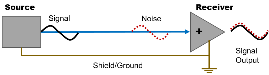
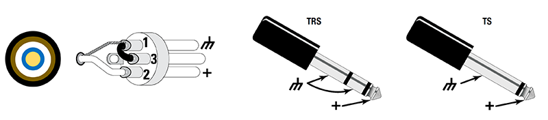
An unbalanced cable consists of two conductors inside a cable connected to a single connector—a signal conductor and a shield/ground conductor. A standard TS (or “tip-sleeve”) guitar cable is an unbalanced cable. Standard RCA cables used in AV components use two unbalanced cables mounted together (red and white phono/RCA connectors).
Inside the cable, the signal conductor is in the center and the ground conductor surrounds it. The shield/ground serves two functions—it carries part of the audio signal (signal return path) and shields the signal conductor from outside interferences such as electrostatic fields, noise or radio frequency (RF) transmissions. When interference induces noise voltage in the shield conductor—which also carries signal—that noise also adds to the signal voltage.
Even if the cable shielding is very good and not highly susceptible to inducing noise voltage, it offers very little protection against electromagnetically induced hum. That is because the cable itself is actually acting like a single-turn transformer, coupling energy from other mains conductors and transformers in the vicinity.
For this reason, unbalanced cables should not be longer than 4-6 meters (15-20 feet), especially when used in noisy environments and with signals that are typically low level, as in keyboards, guitars, MP3 players, etc.
Balanced Cables
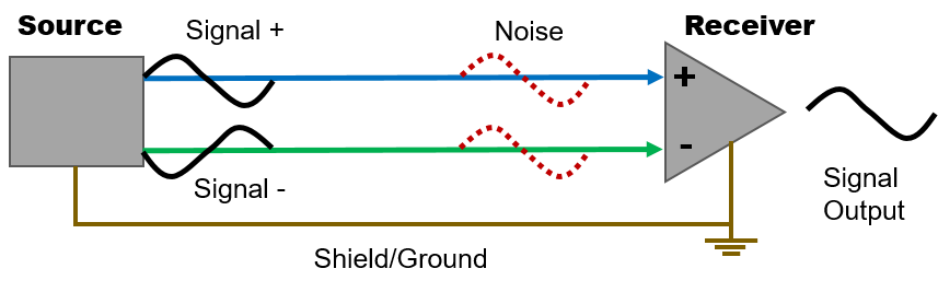
A balanced connection solves this problem by carrying the signal independently from the shield/ground conductor. A balanced cable has a core of two signal-carrying conductors surrounded by the shield. The balanced connection feeds a differential input, meaning the circuit acts only on the difference in voltage between the two signal lines. Any voltage that is the same on both will cancel out, and the circuit will ignore it.
Typically, the signals on the two conductors are an exact mirror image of each other, but contrary to common belief, they do not actually have to be. Some balanced outputs drive the signal only on one side and terminate the other to ground through an impedance equal to the one on the driven side; this is a practice found most often in battery-powered equipment.
What makes the connection balanced is not the symmetry in signal, but both signal conductors having precisely equal impedances to ground. The idea is that any noise that gets into one side will get equally into the other, and they will be canceled out in the differential input. In well-constructed balanced cables, the two signal conductors are evenly twisted to help ensure that their exposure to any electrostatic or electromagnetic noise fields will be equal and therefore canceling.
For the long cable runs commonly found in live sound applications, another type of cable known as Star Quad was developed to further improve the immunity to interference. This shielded cable has four individual internal conductors wired as two parallel pairs. The conductors are arranged alternately and twisted together to better approximate the effect of both signal legs occupying the same space. These Star Quad cables are clearly more effective than conventional balanced cables for mic-level signals.
In general, balanced cables can support long cable runs, typically 15-30 meters (50-100 feet). Standard balanced connectors designed for use with balanced signals are XLR and TRS (or “tip-ring-sleeve”).

Loudspeaker Cables
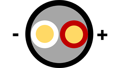
A loudspeaker cable provides the electrical connection between loudspeakers and audio amplifiers. A modern loudspeaker cable typically consists of two insulated stranded copper electrical conductors. One is marked, either on the insulation or with plated strands, for maintaining the correct audio signal polarity. The cable has three key electrical properties: resistance, capacitance and inductance. Resistance is by far the most important one, as it needs to be very low to optimize the transfer of audio power from the amplifier to the loudspeaker’s voice coil.
If the cable resistance exceeds a small fraction of an ohm, it compromises the power amplifier’s damping factor. And because a loudspeaker’s impedance varies with frequency, cable resistance can affect its frequency response. That is because the cable resistance is in series with the loudspeaker impedance, thereby forming a voltage divider that varies the transfer of signal to the loudspeaker with frequency.
The loudspeaker cable’s resistance is proportional to its length and inversely proportional to the cross-sectional area (i.e., gauge) of its conductors. Therefore, it is good to keep loudspeaker cables as short as is practical, but if the situation requires that they be long, then use wires with larger gauge to keep resistance down. A common rule of thumb used by live sound designers is to ensure that the round-trip resistance of the loudspeaker cable be less than 1/20 of the loudspeaker impedance.
Conclusion
Audio cables have only one task, to transmit signals from one end to the other without any loss. This said, it is highly critical to select the correct type of cable for each application, taking into account the cable length required, its overall electrical impedance and the type of devices and signal sources that will be connected to the cable.
Christophe Anet
Latest posts by Christophe Anet (see all)
- History, Development and Applications of Column Loudspeakers - May 30, 2025
- Why is Dynamic Range so important? - May 30, 2023
- Differences between Flown and Floor-Mounted Subwoofer Deployments - May 2, 2023