Introduction: GPIO vs Relay
How do you control power on a device so basic, it runs on batteries? And what can a children’s toy teach us about common mistakes that people make when wiring things using GPIO?
This past April, I presented my Smart Dollhouse at the Girl Scouts of Eastern MA’s annual STEM fest. In honor of the dollhouse’s third trip out into the world, here is some information about how, last year, I was able to control a cheap children’s bubble machine using GPIO and relay modules. I have since added smart plugs that can be controlled locally. More on that later.
First of all, please consider this an open invitation to explore the Q-SYS help file’s section on GPIO: https://help.qsys.com/#Application_Integration/GPIO_Application/gpio_application_overview.htm?TocPat…
They’ve added a ton of new information, including sample wiring diagrams and a page with pinouts. They’ve also put the specifications for every Q-SYS product that has GPIO in one place.
For the purposes of this post, you need to know two things:
- The difference between a GPIO and a relay is that GPIO has a digital output (meaning it tells a device to be on or off), and a relay has an output that physically opens and closes.
- You can damage a GPIO if you don’t wire it up properly. (Don’t wire your bubble machine directly to a GPIO output.)
In any wiring scenario, if you need to physically break a circuit, you’ll need a relay (people get confused about this all the time!) How do you know there’s a relay involved in your wiring? You can hear a little cha-chunk when it switches on and off as the contacts inside it open or close.
Wiring Methods
Last year, I wired my bubble machine to an SRD-05VDC-SL-C relay module and then landed the module on a GPIO output of a QIO-GP8x8. Now, we also have the option of using a QIO-LVR4, so I will show you both wiring methods.
My secret weapon for hard-wiring a children’s toy into my system was to purchase an AA battery eliminator cable. If you look up “AA battery eliminator,” you’ll get a ton of results. You can get a set for less than $10. I confirmed that I could control my bubble machine by cutting and restoring power to it with a simple test: I hooked it up to my battery eliminator and then turned it on and off by plugging and unplugging power.
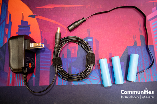
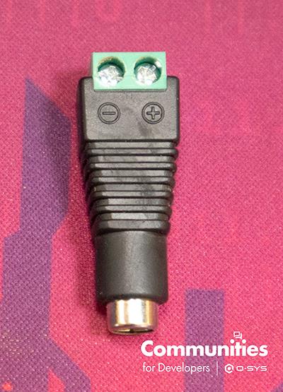
I don’t like cutting the ends off cables unless I must, so I also treated myself to a set of DC plugs to terminal blocks. They’re less than $5 for a set, and they will save you from accidentally ruining a cable by cutting something you weren’t supposed to cut.
Step-by-Step Wiring Guide
Alright, we’ve got all of our gear, let’s see how we wire it up. The basic idea with both wiring scenarios is the same. Use our breakout connectors (those green terminal blocks in the photo) to interrupt power and put a relay in the middle. If the relay closes, the bubble machine turns on. If the relay opens, the bubble machine shuts off.
Note: I’m using non-standard wire colors in my photos below to make it easier to see how everything is wired up. Also, if you would like to see wiring diagrams of similar setups, please check out the help file.
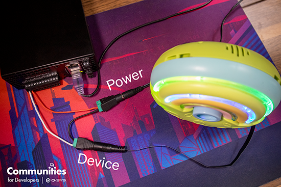
With the QIO-LVR4, I’ve wired the positive of the device to the normally open (NO) pin of the relay. This is the white wire in the photo. I’ve wired the common pin of the relay to the positive of the power cable. This is the red wire in the photo. I’ve wired the negative of the device and the power cables together. This is the black wire in the photo. When the relay closes, the red and white wires are connected, and the bubbles start bubbling.
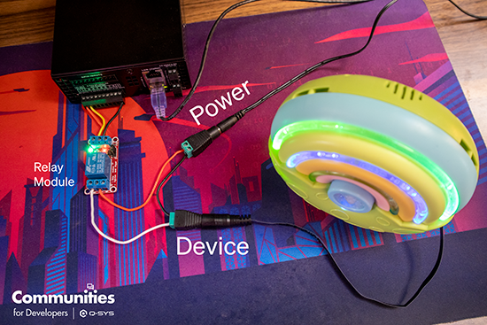
Using a GPIO works very similarly, but we add a relay module between the QIO-GP8x8 and the device. This allows us to interrupt power, with the added benefit of introducing an optocoupler into our system. The optocoupler isolates power and control, preventing us from accidentally frying our Q-SYS box.
Please note that, in my photo, I’m powering the relay module off of my QIO box. All our products with GPIO have different power output specifications (all helpfully laid out in the help file). With the lights in my dollhouse, I have too many relay modules to be powered off of the GPIO block. I use an external power supply for the modules.
In the photo below, the input pin of the relay module is landed on logical output 1 of my GPIO (the yellow wire). It’s powered by landing positive to the 12v DC output (the red wire) and negative to the ground pin (the black wire). If you look carefully in the photo, you can see that these three wires cross over each other.
On the relay side of the module, I’ve wired the normally open pin to positive on the device (the white wire) and the common pin to positive on the power cable (the red wire). I’ve wired the negatives of the power cable and the device cable to each other (the black wire).
This was a great option for me last year. I was presenting at a Girl Scout camp, so I wasn’t guaranteed to have internet access. Using relay modules driven directly from my system meant that I had power controls without having to worry about cloud controls.
Using Smart Plugs
This year, I added a couple of smart plugs that can be controlled locally. Kevin Rhodus clued me into Shelley Plugs, which have a local API. Eugene Dunn also gave me a plugin he wrote to control TP-Link/Kasa Smart devices locally. So now, I plug the bubble machine directly into a smart plug and call it a day. It makes setup so easy, I’ve added a mini Wacky Wavy Inflatable Arm Gal.
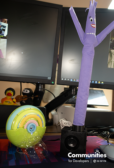
Ever since I’ve added the bubble machine, it’s been the star of the show! It’s so popular, I think I need an automation that shuts it off after 30 seconds.
What are some human sized automations that you could add to a system with the above techniques? This post comes to mind: https://developers.qsc.com/s/question/0D5TO000009eQA50AM/any-recommendations-for-an-on-air-led-light…
I’d love to hear some other ideas from the Community!
Hope Roth
Derniers articles parHope Roth (voir tous)
- Citizen Spotlight: John Walsh Brings AV Magic to Bates Motel - October 30, 2025
- Integration Spotlight: GPIO and Relay Controls - October 14, 2025
- How a Smart Dollhouse Inspires the Next Generation of AV Innovators - December 5, 2024
