
Five Common Errors in Q-SYS Training
Have you experienced our Q-SYS Level One for Cinema training course?
If you aced it with the greatest of ease, you are among the few. Less than 5% submit a flawless design for their exit exam. Having graded hundreds of these you can imagine I have a feel for the issues that stump many students. Hopefully light will be shed today.
1. Connecting Amplifiers to Loudspeakers
Let’s start with an easy one. It’s something people don’t expect to be an issue but would wreak havoc with your audio if done incorrectly. The issue is incorrectly connecting, virtually, the wires from amplifiers to loudspeakers. In Q-SYS, one amplifier might receive the same signal into each channel and distribute it to multiple sections of the same 2, 3, or 4-way loudspeaker, each configured in the amplifier or loudspeaker’s crossover filters to reproduce a different band of frequencies (lows, mids, highs, etc.).
What you might not expect is that each input pin on a loudspeaker voicing component in Q-SYS has a pre-configured frequency band assignment (LF, MF, HF, VHF).
This is because these loudspeaker components contain voicing data, including crossover information, which is sent to the amplifier (see “Getting Started with Q-SYS”). Once processed inside the amplifier it is sent to the loudspeaker through physical wires. So when a signal leaves the amp it only contains the frequencies meant for that particular channel/loudspeaker. You wouldn’t want to send subwoofer frequencies to a HF driver, now would you? So you have to match them correctly in Q-SYS from the amp block to the loudspeaker voicing block.
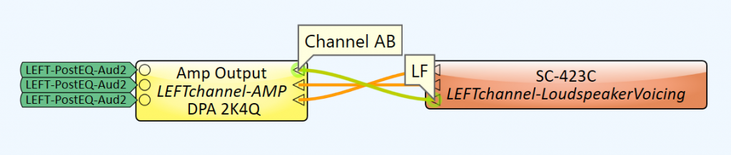
This could be a big deal, especially when an amplifier has two channels set to bridge or parallel mode, as in the graphic above. In this case, you must know that these combined channels (AB or A+B) are intended to be routed to the LF input pin of the loudspeaker voicing component, not the HF pin directly across from it. Connecting top pin to top pin is a common snafu and could damage your drivers.
You may be asking why we designed it this way. Well, we thought it made more sense putting the “High Frequency” pin higher and the “Low Frequency” pin lower on the loudspeaker component. It was that simple.
2. Tools > Unlock All
Here’s another easy one. Students are asked to copy the template design onto another schematic page to create a 2nd auditorium. But when all items are selected, copied, and then pasted, some of the items don’t copy over. Some cannot be copied and it’s easy to understand why. Using one Core you will only have one of each of its components. You can’t copy these. Same for the DCIO/DCIO-H. This peripheral is your primary on and off ramp for I/O in cinema. You need a separate DCIO for each auditorium.
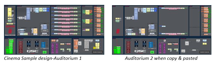
The status components for your amps and peripherals won’t copy over because those amps and peripherals belong to Auditorium One. The snapshot banks don’t copy over either. But the kicker that generates injurious notes in my inbox is the EQ chains. Some copy over, some don’t. What’s the deal? Here’s a freebie: select Tools > Unlock All before you copy and paste.
You’re welcome.
Q-SYS has several ways you can protect the elements in your design. This is one of them. It’s a good feature to know about.
3. Loudspeaker Monitor Component
Those were two easy ones which lead to a big one.
Another element that is not copied into our second auditorium is the Loudspeaker Monitor component of the Core. In the exam we ask you to use this one component for both auditoriums. This component is explained in the Level 1 curriculum. Using it for two or more auditoriums is not.
This lesson starts with an explanation of what this component does. The Loudspeaker Monitor component provides the means to get a signal from the loudspeaker to an output suitable for monitoring, i.e., your booth monitor.
In Q-SYS, each loudspeaker voicing component, contains a Listen button, actually one main and one for each frequency band if it is a 2, 3, or 4-way loudspeaker.
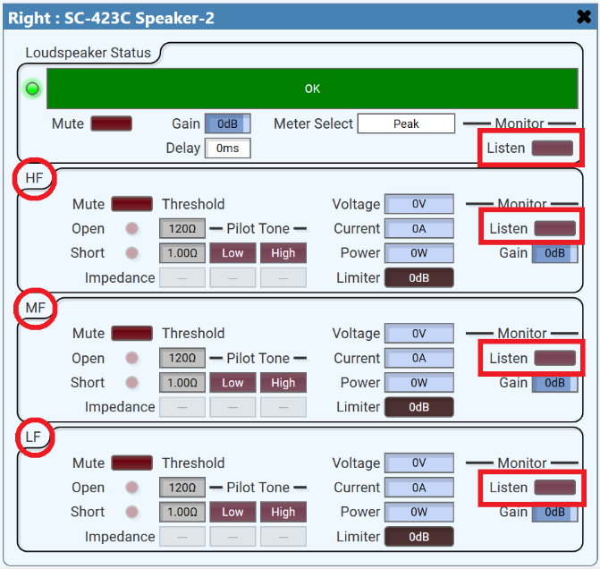
When one of these buttons is pressed its signal is routed through the one and only Loudspeaker Monitor component and sent ultimately to a booth monitor. It’s an effective way to troubleshoot and monitor your audio.
But if you have two auditoriums and only one Loudspeaker Monitor what keeps you from pressing a listen button in Auditorium One and hearing it in the booth in Auditorium Two? Something needs to tell Q-SYS which Auditorium’s booth to ROUTE this signal to. This requires, you guessed it, a Router.
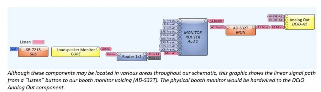
The solution includes adding a router after the Loudspeaker Monitor, which will direct its output wherever you send it, to Aud. 1 or Aud. 2. It’s simple enough to select the appropriate router button and the desired loudspeaker listen button and poof!, there you have it. But can we just press one button that will select them both? We can.
It is not difficult to create a new snapshot bank with snapshots that choose the appropriate router setting and listen button combined. One snapshot for each loudspeaker component in your design (or even one snapshot for every frequency band).
*You may notice in the graphic above that via the “Monitor Router” we have created the ability to route Pre-Processed signals to the booth monitor (AD-S32T) as well.
4. F.A.S.T. (Flexible Amplifier Summing Technology)
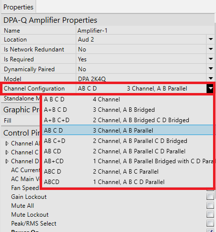
Incorrectly configuring amplifier channels is another common mistake. Using 4-channel amps in our design we specify that two of the channels be combined in Parallel for the low frequency drivers (LF). Many select Bridged mode by mistake or because this is a standard operating procedure among veterans. However, our testing confirms that due to the capability of the high voltage rails on new DPA-Q amplifiers (used in this exam,) Parallel is a more effective option. When configuring an amplifier, go to its properties panel and choose “Channel Configuration.” A+B is Bridged. AB is Parallel.
5. Balcony Mix
Lastly, regarding the new balcony loudspeakers we ask you to add in the exam. These need the ability to be delayed so that their signal will arrive relative to the signal emanating from the Screen channel loudspeakers at the front of the auditorium. These delays are built into the template design at the end of each channel’s signal chain. We ask students to add additional “delay taps” to the delay components of the side and rear surround channels and mix them together to create signals that will be routed to the balcony. I can feel the despair when I’m grading. It’s easy now, but I remember in the heat of battle taking my own exam, it was not. Although we specify one method, there are plenty of ways to accomplish this and many other tasks in Q-SYS. It is remarkable like that.
Here’s an approach we think is practical.

Additional Delay taps (set to 0ms delay) can be added to a delay component via its Properties panel. Signals from these taps can be mixed and delayed using a Delay Matrix Mixer and sent to the amp feeding the balcony speakers.
Using the graphic above, let’s examine our Left Side Surround signal. Tap one is sent to one amp channel and feeds a few surrounds, Tap two to another amp channel for surrounds farther down the side wall, and the third tap gets mixed with the rear surround signal, delayed, and sent to another amp channel powering the new loudspeakers in the balcony.
One Last Thing
Keep it simple. More often than not, easier is better. Obvious is better. Neat and clean is better in Q-SYS. Remember that at some point there may be another technician who will encounter your design. Take advantage of the Graphic Tools included in Q-SYS and add notes in text boxes beside anything that might need explaining. The easier your design is to navigate, the better.
Are there other stumpers on the exam or with Q-SYS in general that we can help clarify? We want you to have all the resources you need, so tell us what would help you in your work with Q-SYS and we’ll do our best to accommodate. And please let us know if this post was helpful in the Reply section below.
Britt Wilson
Derniers articles parBritt Wilson (voir tous)
- Train Now for Cinema’s Comeback - September 14, 2021
- Help is Here - July 20, 2021
- Four Quick Tips for Cinema Applications - April 29, 2021