This blog article is going to first explain and illustrate the various challenges of setting up a cardioid subwoofer array yourself, before revealing how QSC subwoofer solutions achieve outstanding results.
Let’s begin by defining what we mean by subwoofer? A subwoofer – or ‘sub’ – is a complete loudspeaker dedicated to the reproduction of low-pitched audio frequencies known as bass. They are intended to augment the low frequency range – typically between 20 Hz and 120 Hz – of the main loudspeakers covering higher frequency bands.
Some History
In the mid-1950s, various hi-fi loudspeakers’ manufacturers started to introduce compact, sealed enclosures that had long-throw type woofers. Subwoofers came into popular awareness with the introduction in the 1970s of SenSurround in movies such as ‘Earthquake’. With the advent of the compact cassette and the compact disc in the 1980s, the easy reproduction of deep and loud bass was no longer limited by the ability of a phonograph record stylus to track a groove. Hence, subwoofers became increasingly popular. During the 1990s subwoofers were found in home stereo systems, custom car audio installations and in PA systems. By the 2000s, subwoofers became almost universal in sound reinforcement systems in nightclubs and concert venues.
The Standard Subwoofer Radiation
The waves of sound radiated by a conventional subwoofer display a spherical pattern unless they are interfered with by a solid surface or by opposing pressure. So, below 200 Hz the energy radiated by a subwoofer is fully omnidirectional and this is because the directivity of a subwoofer is related to the ratio of its size to the length of the sound wave it produces. The length of the sound wave is inversely proportional to its frequency, and therefore when the low frequency waves are much longer than the dimensions of the subwoofer transducer and enclosure, the radiation pattern becomes similar in all directions, including to the sides and back.
The following figure illustrates this with a measurement of two standard subwoofers facing forward and measured together. It displays the standard radiation of any subwoofer – unless it is a cardioid one. Bass energy radiates into all directions, in any setting, indoor or outdoor. This can result, for example, in too much bass energy radiating into musicians’ microphones or low frequencies disturbing another event nearby.
The x-axis shows frequencies, the y-axis displays radiation angle (zero is on-axis) and the amplitude of the signal is color-coded (all plots graphically show 0 dB as normalized maximum amplitude for each frequency).
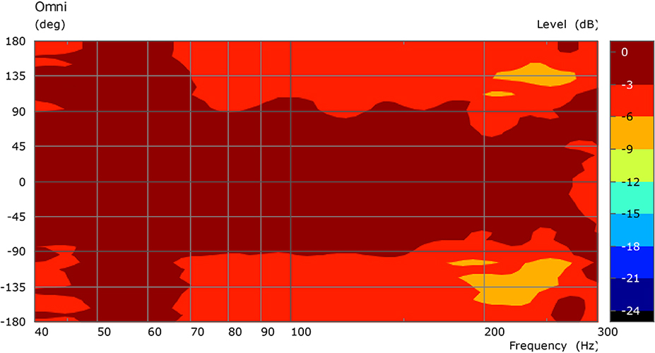
Figure 1 – Directivity characteristics of two omnidirectional subwoofers, oriented in the same direction with identical EQ applied, measured at 4 m.
The Directional Cardioid Solution
Now, as we have all witnessed low frequencies omnidirectional radiation can sometimes be problematic, as it may cause feedback, create bass build up in some part of a room or disturb neighbors. Since the late 50’s sound engineers have setup subwoofer’s array – a minimum of two units. Such setups require careful adjustments of delay, polarity, output levels and distance between the units, to force the radiated energy to become directional. The term cardioid radiation – or heart-shaped – refers to the shape of the directional coverage in which levels are louder to the front of the unit and lower behind it.
However, to implement proper cardioid radiation, the adjustments of the above-mentioned parameters must be applied with an appropriate understanding of the laws of physics. This has been a challenge for many sound engineers and production companies for years.
Assembling a Cardioid Array Yourself
To illustrate the challenges one can have to implement cardioid radiation using two subwoofers, let’s look at one parameter at a time. The various cases below use a cardioid subwoofer arrangement with front and rear-firing woofers.
1. Polarity Inversion and Delay
In this first case, we have inverted the polarity between the woofers (180-degree phase-shift on the rear woofer) and added an appropriate delay value between the woofers (note that the delay is fixed over the entire subwoofer bandwidth).
As a result, the coverage is varying between 180° at 50 Hz and 270° at 150 Hz. Looking at the strange horseshoe shape graph below one can see that the subwoofer is not usable above 140 Hz (black line). In addition, the cardioid ‘cancelation’ is only effective below 70 Hz (blue areas). This means that such a subwoofer array will be cardioid at very low frequencies, but less and less so as you increase frequencies. In this compromised case, too much bass is still radiated towards undesirable areas.
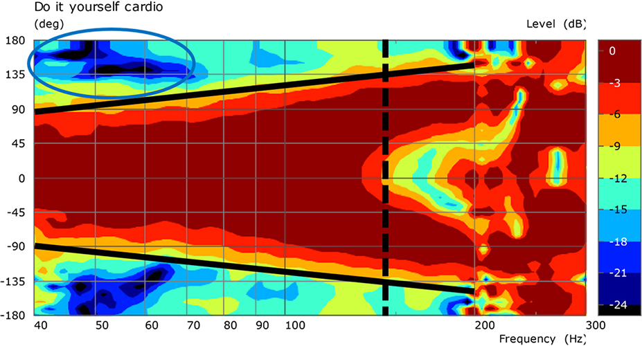
Figure 2 – Cardioid directivity characteristics of two subwoofers with inverted polarity and single delay value applied, measured at 4 m.
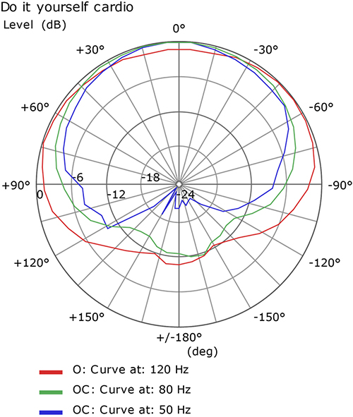
Figure 3 – Cardioid directivity characteristics of two subwoofers with inverted polarity and single delay value applied, measured at 4 m.
2. Too short Delay Setting
The second example features a delay setting between the woofers that is too short. In this case, the forward radiation is improved and better controlled but unwanted rear radiation (rear lobes) completely spoil the cardioid ‘cancellation’ effect. This means that the bass attenuation to the side of the subwoofer is fine whilst a lot of bass energy is still radiated to the back. This setup is, once again, not optimal, as our original target is not reached.
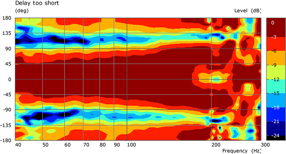
Figure 4 – Cardioid directivity characteristics of two subwoofers with inverted polarity and too short delay value applied, measured at 4 m.
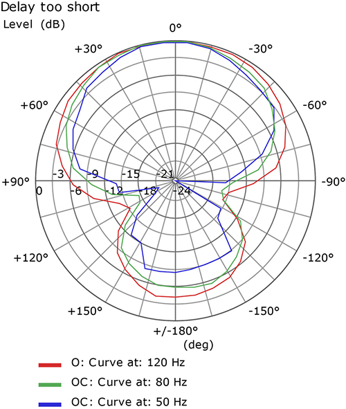
Figure 5 – Cardioid directivity characteristics of two subwoofers with inverted polarity and too short delay value applied, measured at 4 m.
3. Too long Delay Setting
Inversely, if the delay between the two woofers is too long, the bass attenuation to the sides is not very effective and the bass radiation becomes again almost omnidirectional in the upper subwoofer bandwidth. Too much bass energy is still wasted into the open area behind an outdoor party or into musician’s microphones.

Figure 6 – Cardioid directivity characteristics of two subwoofers with inverted polarity and too long delay value applied, measured at 4 m.
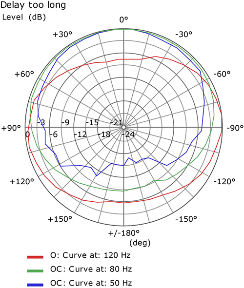
Figure 7 – Cardioid directivity characteristics of two subwoofers with inverted polarity and too long delay value applied, measured at 4 m.
The QSC Cardioid Solutions
In order to overcome the adjustment difficulties encountered when trying to set up a cardioid array, QSC developed user-friendly products and solutions to guarantee perfect cardioid radiation at all times. QSC’s latest DSP technology performs the complex processing that makes mirrored woofers interact at the rear of the enclosure(s) to produce a desirable cancellation, while simultaneously interacting at the front of the enclosure(s) to produce equally desirable summation. As a result, the radiation pattern displays an ideal cardioid shape, with 15 dB higher level at the front than at the rear.
Two QSC KS Series active subwoofers feature cardioid radiation patterns. The compact and lightweight KS212C, powered by a dual 1800-watt Class D amplifier, is a single box cardioid solution incorporating dual 12-inch long-excursion drivers. New in the range, the very high-output KS118 is powered by a 3600-watt Class D amplifier driving a single 18-inch direct radiating driver. Its on-board DSP menu offers the option of arraying two or more units in a forward/backward cardioid arrangement.
Therefore, thanks to advanced on-board DSP processing, when the correct spacing, polarity, output levels and delay between the woofers are applied, it is possible to implement an efficient cardioid radiation. Having the complete control on the subwoofer’ topology and EQ (especially for the KS212C where the distance between drivers is fixed) allows us to precisely tailor a cardioid DSP filter where delay and amplitude corrections are dependent of frequencies to achieve optimized cardioid radiation over the entire useable bandwidth. In doing so, both the rear attenuation as well as the on-axis sensitivity are optimized.
With such solutions, we keep ‘bass in its place’ on the stage, avoiding bass radiating into musicians’ microphones, or on the dancefloor, stopping walls to rattle and to annoy other quiet nearby parties.
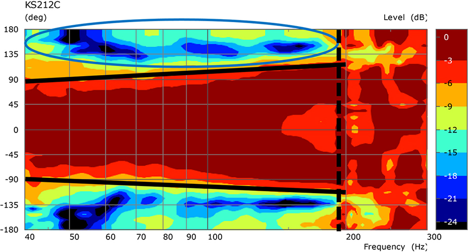
Figure 8 – Cardioid directivity characteristics of QSC KS212C Cardioid Active Subwoofer, measured at 4 m. The blue areas indicate the rejection. The black lines highlight the usable range.

Figure 9 – Cardioid directivity characteristics of QSC KS212C Cardioid Active Subwoofer, measured at 4 m. The blue areas indicate the rejection. The black lines highlight the usable range.
Conclusion
With practice and experience, it is possible to set up a subwoofer array with additional electronics to implement a correct cardioid subwoofer radiation. However, failing to adjust precisely the necessary parameters – namely spacing, delay, polarity and output levels – will result in much compromised subwoofer array performances.
In order to simplify the setup work and make sure all QSC customers benefit, whenever needed, from perfect cardioid subwoofer radiation, we developed user-friendly products and solutions for a multitude of critical live sound applications.
Acknowledgment
Great thanks to Rémi Vaucher, QSC Senior Technical Director, for his valuable notes and all the measurements he provided for this article.
Christophe Anet
Latest posts by Christophe Anet (see all)
- History, Development and Applications of Column Loudspeakers - May 30, 2025
- Why is Dynamic Range so important? - May 30, 2023
- Differences between Flown and Floor-Mounted Subwoofer Deployments - May 2, 2023
What happens if I set both KS118 subs to “Front Mode Cardioid” and set them up on each side of my DJ booth under my pole mounted HF cabinets? Will there be better bass on the dance floor given the rear rejection? Will this also reduce the power alley between the subs?
Hello Tommy, thanks for your question. The Front/Rear cardioid mode settings only work when they are applied together. Various adjustments are happening in the electronics to create an efficient cardioid pattern. Using only the Front setting will not help in any way. On the contrary your sub(s) will feature a compromised sound quality. The Cardioid mode works when using two KS118 linked together via the cardioid preset settings. All the best. Cheers, Christophe Anet.